CUSTOM-MADE THERMAL COVERS FOR INDUSTRY

Technical characteristics of thermal covers
| Symbol | Features | Units | Values |
|---|---|---|---|
 |
Thermal conductivity | W.m-1.K-1 | 0,047 to 100° |
 |
Maximum basic operating temperature | °C | 300°C |
 |
Thermal Resistance (e = 60 mm) | m².K/W | 1,5 (70°); 1,2 (90°); 1,0 (110-120°) |
 |
Reaction to Fire | Euroclass A2-s1, d0 |
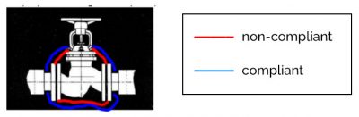
Some examples of thermal covers suitable for industrial piping accessories


Recommendations to follow for effective insulation
Symbiote, a business union specializing in the energy renovation sector has drawn up a list of recommendations that must be followed.
Positioning of thermal covers and junction with the insulation
The insulation of singular points by installing insulating covers is a separate action: the insulation of accessories and the insulation of pipes (insulation) are separate and do not interfere with each other and have their own technical characteristics and implementation methods. These are two independent systems. Thus, thermal covers are supplied and installed by the installer/operator of a thermal installation independently of the insulation of the installation.
The thermal cover completely envelops the singular point as well as its connection system up to the weld of the flange on the pipe or union side in compliance with the clauses of § 8.1.2.3 of NF DTU 45.2 P1-1 [Insulation work – Thermal insulation of circuits, devices and accessories from – 80 °C to 650 °C] which clearly stipulates the reservation between the insulation and the flanges. The thermal cover is independent of the insulation of the pipeline whatever its condition, dimensions, performance, future or eligibility for CEE. In the case of flanged equipment, the physical limits of the singular point are the two connection welds upstream and downstream of their counter-flanges.
The cover must allow access to the equipment without removing it. NF DTU 45.2 P1-1, (NF P 75-402-1-1), of May 2006 – Thermal insulation of circuits, devices and accessories from -80°C to +650°C – § 8.1 clearly states the shape of the thermal cover depending on the positioning of the insulation, recalling that the tube insulation is stopped at a distance such that the disassembly and reassembly of the bolts can be carried out normally.
This arrangement of the correct insulation of a singular point is supported by a diagram developed by Filiance (guide n° 19 – Inspection of standardized energy saving operations COPREC JUNE 25, 2020-) which is clear and judiciously uses the insulation guard gap of a few cm upstream of the singular points: